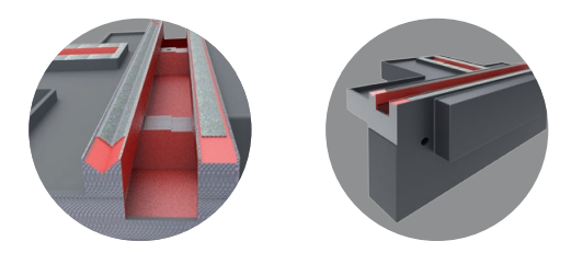
Bed
The basic parts of the machine bed are made of high-quality grey cast iron. Given the high demands of grinders as regards dimensional stability of castings, strength and vibration damping we use GG 25 cast iron for manufacturing the load-bearing parts of the machine tools. Before the casting is used in the machine, it is heat-treated several times to provide very precise machining of the machine bed. High rigidity of an ideally dimensioned cast-iron machine bed guarantees a high performance and productivity of the machining process while at the same time ensuring first-rate geometric accuracy of the workpiece. Having been machined, all the essential areas of the machine bed are ground manually for the required accuracy. The scraping areas, on which the table and wheel-head are located, is moved on the manually ground slide ways. If the table is divided, it enables the workpiece to be turned within the given range. The ways are lubricated by an automatic lubrication system that combines hydrostatic and hydrodynamic lubrication. The table with the work head and tailstock is moved on the front bed, while the wheel head is located on the rear bed. The table has two parts, lower and upper. The lower table moves horizontally in the ways on the bed. Its travel is carried out by a ball screw and servomotor with a special flexible coupling. The upper table can be tilted to compensate for cylindricality aberrations. A micrometer indicator is used for fine adjustments
Wheel-head
Wheel-head box consists of a rigid casting made of high-quality grey cast iron. The grinding spindle goes through the whole grinding wheel-head unit. The grinding wheel-head is characterised by rigidity and accuracy of the grinding spindle, which is placed in radial hydrodynamic flexible slide bearings and in an axial slide bearing. The leading wedges of the radial bearings are formed by the bearing shell being deformed by the constant pressure of the spring. The bearing areas of the spindle are surrounded by an oil film in three places evenly placed around the circumference. Apart from the sliding mount of the wheel-head grinding spindle we also make a rolling mount. That is carried out by very precise and accurately adjusted spindle ball bearings. The lubrication of the grinding spindle bearings is circulating, using a separate tank. The lubrication system is fitted with electric indication of lubrication oil flow, which shuts down the grinding wheel drive motor if there is insufficient flow. In order to ensure thermal stability the headstock is fitted with a cooling system. The drive of the grinding spindle is ensured by a three-phase asynchronous motor located on the wheel head’s body top. The torque between the motor and the grinding spindle is ensured by a belt drive. The wheel-head grinding is located on the carriage ensuring its cross feed on the X axis. The movement of the carriage along the X axis is carried out by a servomotor and an accurate ball screw. The maximum accuracy of the X axis is ensured by a linear optical ruler. The wheel‑head grinding can also be tilted within the given range. The grinding wheel is covered by a safety cover that ensures the grinder’s safety and prevents the cooling liquid from spurting out. The angle of the cover opening and the thickness of the walls of the cover comply with the ČSN EN 13218 standard. The whole cover consists of the base unit and opening lid secured by the end switch, which prevents the grinding spindle motor from being turned on when the cover is open.
Work-head
The work-head is used for clamping and rotating workpieces. The plate with the work-head is attached to the grinder’s table by two T-bolts and nuts. The base of the work-head consists of a casting made of grey cast iron in which the spindle is placed. This placing consists of accurate rolling bearings and is adjusted to comply with the prescribed geometrical tolerances even at the highest load. The drive of the spindle (C axis) is ensured by an asynchronous motor or by a servomotor (controlled axis). The body of the work-head can be turned towards the wheel-head grinding by 90° at the most according to the scale. The work-head is designed universally to make it possible for a fixed centre to grind between centres, a chuck to grind workpieces clamped on one side, an obverse plate or electromagnetic plate with permanent magnets or special clamping devices to be clamped.
Tailstock
The tailstock is used for clamping workpieces between the centres. It is attached to the upper table by two T-bolts with nuts. During set-up, after the nuts have been loosened, the tailstock is moved along the upper area of the upper table. The pinole in the tailstock body is placed slidingly. Its movement along the axis is pneumatic – controlled by an electric pedal or mechanically. In the tailstock there is a conical hole for Morse clamping centres. The clamping power of the centre affecting the workpiece is adjustable and is controlled by the pressure of a spring. The tailstock is fitted with a device to provide fine compensation for the workpiece’s cylindricality enabling the centring of the pinole within a small range. The holder of the central dressing unit which forms grinding wheel is mounted on the rear part of the tailstock.
Control system and control panel
The whole grinding process is controlled by a control system. As a standard the machines are fitted with CNC control system Siemens Sinumerik 840 D sl or, upon the customer’s request, with the Kavalír K51-2 NC system. All machine control features are located on the main panel. All controls are clearly and ergonomically designed. The electric cabinet is located behind the machine. There are control and performance features in the cabinet, whose arrangement is in compliance with the respective safety standards and complies with the EMC tests.
Covers
The cover of UB 25 is designed to meet all environmental, ergonomic and safety standards. The main emphasis is put on the safety of operation. The cover ensures the operator’s safety. Through a window the cover makes it possible, , to control the working process optimally, to change the workpiece and the grinding wheel and to carry out maintenance and servicing. All cover parts are in compliance with ČSN EN 13218. Another function of the cover is to conduct the emulsions back into the filtration tank and to prevent its leaking into the environment as a liquid or aerosol. The same purpose is served by the extraction system of the bonnet area. Last but not least, the cover also has an aesthetic and design function helping the operator to feel good and safe.
