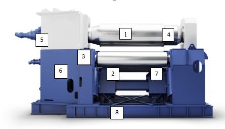
| The machine is mainly composed of an upper roller device (1)Lower roller device(2)Side roller device(3)Tipping device (4)Balancing device(5)Left and right side frames (6 、7)Chassis(8)Lubrication system, Hydraulic system and Electronic control system. |
|
|
|
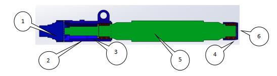
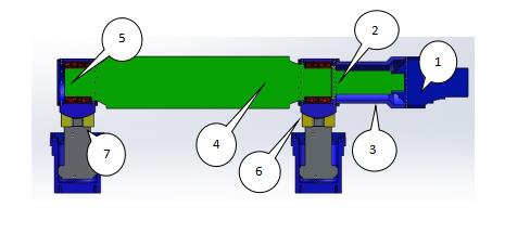
Upper roller device
The upper roller device is composed of a main hydraulic motor(1)Coupling (2)Connecting Sleeve(3)Connecting Sleeve (4)Upper roller (5)Tipping Sleeve and(6)。
The main hydraulic motor (1) is equipped with an instant brake device with a pressure level of 25MPa.
The double-row spherical bearing (4) adopts a low-speed, heavy-load spherical roller bearing.
|
|
 |
The upper roller (6) is drum-shaped. When designing the upper roller, the load coefficient of the maximum pressure of the upper roller is 0.5 uniformly distributed to pre-set and compensate for the deformation of the upper roller under stress.
The material of the upper roller (6) is alloy steel 42CrMo, quenched and tempered after rough machining, HB280-300, according to the JB/ZG4289-86 rolling roller steel standard, the rigidity meets (1/700~1/1000)L L—refers to the distance between the center lines of the two sides of the frame.
|
|
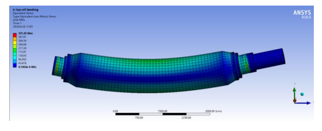
Upper roller stress cloud diagram
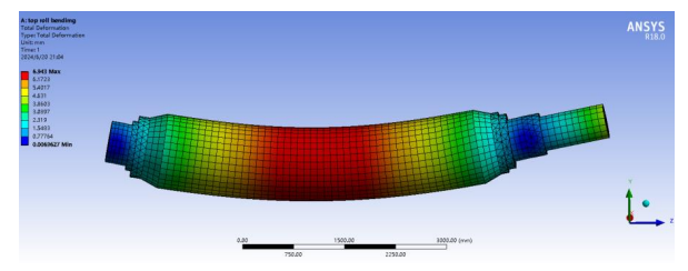
Upper roller strain cloud diagram
|
|
Lower roller device
The lower roller device consists of a lower roller motor (1), a lower roller coupling (2), an auxiliary transmission coupling frame (3), a lower roller (4), a lower roller double-row self-aligning bearing (5), a lower roller bearing seat (6) and a lower roller bearing support seat (7). The auxiliary hydraulic motor (1) is equipped with a brake device, and the pressure level is 25MPa.
The two lower roller main cylinders provide the pressure required for rolling the plate, and the working pressure of the main cylinder is 25MPa. 。
The lower roller (4) is made of alloy steel 42CrMo, HB280-300, and is quenched and tempered after rough machining. According to the JB/ZG4289-86 rolling roller steel standard, the rigidity meets (1/700~1/1000)L L—refers to the distance between the center lines of the two side frames.
The lower roller (4) is drum-shaped. When designing the lower roller, the load coefficient of the maximum pressure of the lower roller is 0.5 uniformly distributed to pre-set and compensate for the deformation deflection of the lower roller under stress.
The auxiliary hydraulic motor of the lower roller (4) transmits torque to the lower roller (4) through the coupling (2). The lower roller bearing seat support seat (7) adopts ZG350. The double-row spherical bearing (5) adopts low-speed, heavy-load spherical roller bearing.
|
|
 |
|
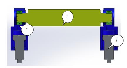
Side roller device
The side roller device consists of a side roller cylinder (1), a double-row spherical bearing (2) and a side roller (3).
The side roller cylinders (1) provide the side roller pressure required for rolling the plate, and the working pressure of the main cylinder is 25MPa.
The double-row spherical bearing (5) adopts a low-speed, heavy-load spherical roller bearing.
The side roller (3) is made of alloy steel 42CrMo, HB280-300 after rough machining and tempering treatment. According to the JB/ZG4289-86 rolling roller steel standard, the rigidity meets (1/700~1/1000)L L—refers to the distance between the center lines of the two side frames.
|
|
|
|
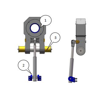
Tipping device
The tipping device is composed of a tipping bearing seat (1), a tipping cylinder (2) and a pin (3).
The device drives the tipping frame to tip over and disengage the tipping end of the upper roller through the oil cylinder and hinge, so that the product can be taken out.
|
|
 |
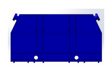
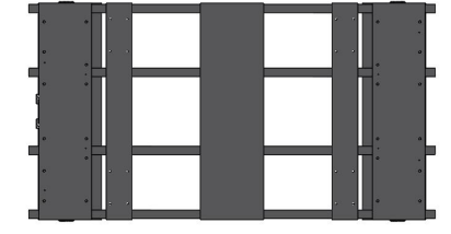
Body
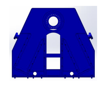
side rack
|
|
Tip-over side rack
|
|
Chassis
The machine body consists of a base, a fixed side frame and a tipping side frame. Each part adopts a steel plate welded structure, which has the advantages of light weight, low cost, good processability and short production cycle.
The frames on both sides are fixed to the base by bolts with flat keys, and theframes on both sides are connected together with a connecting beam to make the whole machine rigid.
The two side frames are equipped with moving guide rails for the lower roller and the side roller, the fixed side frame is equipped with the upper roller bearing seat, which is a closed frame structure, and the overturning side frame is equipped with a supporting device for the overturning frame. The force during the rolling process is borne by the two side frames.
The base not only supports the weight of the machine and ensures the accuracy of the equipment, but also connects the whole machine into one. It is designed for heavy-duty welded box beams, with sufficient strength and rigidity to withstand the maximum downward force at the maximum load. The mounting surfaces of the edges of the frame and other components are processed.
|
|
 |
Lubrication Method
The lubrication system of this machine adopts three methods according to the working conditions: oil immersion lubrication, automatic centralized lubrication and regular oil lubrication. The planetary reducers of the upper and lower roller main drive adopt oil immersion lubrication.
Selection Of Lubricating Oil
Manual regular lubrication points use No. 1 lithium-based grease (GB7324-2010), and automatic centralized lubrication uses No. 000 lithium-based grease (GB7323-2010). The planetary reducer uses 220# industrial gear oil.
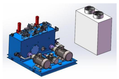
Hydraulic System
Hydraulic Station
General Overview
The functions of the hydraulic system include: driving the rotation of the upper and lower rollers; driving the vertical and inclined lifting movements of the lower and side rollers; and the tilting and resetting movements of the tipping frame.
The lifting displacement of the lower and side rollers can be precisely controlled, and the working rollers can be stopped at any position. The machine is equipped with a hydraulic circuit that ensures synchronized rotation and consistent linear speed of the rollers, enabling fast and accurate straightening and positioning of the workpiece before rolling.
The hydraulic control system adopts an integrated valve block design for easy maintenance, ensuring excellent functionality and operational reliability. It includes oil filtration and an industrial chiller cooling system. No oil leakage is allowed in the entire hydraulic system.
|
|
|
|
The hydraulic piping layout is neat and user-friendly; the bends of the metal oil pipes are natural and reasonable.
The hydraulic oil tank is equipped with an industrial chiller to reduce and stabilize oil temperature, which must not exceed 45°C. Hydraulic components are selected from top-brand products to ensure long-term, leak-free operation.
To facilitate commissioning and maintenance, suitable pressure testing points and air release heads are provided on the hydraulic unit and pipelines.
The hydraulic station, components, and pipelines are all permanently and clearly labeled, consistent with the drawings, and a detailed troubleshooting guide for common faults in the hydraulic system of the plate rolling machine is provided.
The hydraulic system is equipped with suction and return oil filters to ensure system cleanliness, and an air filter to prevent moisture from entering the oil tank.
The system is composed of a plunger pump, valve group, fluid connectors, and hydraulic accessories. Stacked valve series are used for the hydraulic valves, with a simple pipeline layout for easy maintenance and debugging.
|
|
The system consists of four circuits: overpressure protection and pressure regulation circuit, synchronization circuit, speed control circuit, and working roller speed control circuit.
The pressure regulation circuit adjusts the system working pressure through the main relief valve.
The working pressure is 25 MPa. The synchronization circuit uses an electro-hydraulic proportional valve to synchronize the up and down movements of the lower and side rollers.
Displacement sensors are used for detection, with the positioning accuracy of the upper roller being ±0.10 mm.
The speed control circuit regulates the tipping and resetting speed of the tipping side through throttle valves. Servo technology is applied to control the flow via proportional valves, adjusting the working roller speed.
|
Protections
The hydraulic system has monitoring functions to supervise key pressure output points and oil temperature. In case of a malfunction, the system will automatically shut down and issue an alarm, indicating the fault location.
Overflow valves are installed for the upward and downward movements of the lower and side rollers to provide limit protection.
Electrical
Control System The control system is a dedicated control solution developed and manufactured by Ezhong for the fully hydraulic four-roll plate rolling machine. It is composed of the main electrical cabinet, control unit, hydraulic station, and mechanical actuators
The control unit collects various data through sensors for displacement, pressure, and temperature. The data is processed and logically controlled by a PLC (Programmable Logic Controller), and the real-time equipment status is displayed on an industrial touch screen.
This system is advanced in design, flexible in operation, safe and reliable in operation, and has good fault tolerance. It can continue to function reliably even when disconnected from a computer.
Functions of the Control System:
Display Functions:
Real-time measured data of the displacement, tilt, and pressure of the two main cylinders, horizontal displacement of the lower roll, and pressure of the balancing cylinder are displayed on the screen.
The data is visually represented with graphical and pointer-style pressure gauges to show both actual and limit values. The working status of each hydraulic solenoid valve is displayed: powered (red), unpowered (green).
The identifiers and layout of solenoid valves on the screen match those on the hydraulic station. The red and green signals correspond directly to the LEDs on the solenoid valves, aiding in fault analysis and inspection.
The speed detection window for the main cylinders allows monitoring the rising/falling speed of the left and right cylinders, enabling manual synchronization adjustment. The microcomputer system provides a rich display interface: pressure and displacement data are shown in real-time in color with graphics; PLC input status and each solenoid valve status are represented by green indicator lights (lit when energized, off when de-energized); alarms for limits and thresholds are highlighted in red in the lower-right section of the screen.
System Parameter Modification Function
Clicking on "System Parameter Settings" allows system parameters to be modified. This feature is password protected to prevent accidental or unauthorized changes, and only accessible by system administrators.
Process Parameter Storage Function
The system can store process parameters for different workpieces in a specific sequence. Users can retrieve stored process data for use in the program control interface at any time.Mature process parameters can be stored and reused as needed.
Software Protection Function
In addition to various limit switches and protective components, the electrical control system has software protection capabilities. It monitors and controls extreme positions of rollers, cylinder pressure limits, hydraulic oil level, oil temperature, and filter clogging status.
When rolling small or pre-bent workpieces, the operator can set a custom insurance pressure (lower than the machine’s rated maximum) based on the calculated load, ensuring safe operation.
Human-Machine Interface Function
The system provides comprehensive user assistance, including:
- Full set of user manuals
- Hydraulic circuit diagrams
- Electrical schematics
- Lubrication charts
- Safety operating procedures
- High/low voltage operating instructions
- Hydraulic and electrical troubleshooting guides
- Original instruction manuals for key components
- List of wearing parts with part numbers
- Specifications and manufacturers of key supporting components
- Original test data recorded during installation and commissioning for future reference by the end user during operation and maintenance.